SOLDERING
2. Solder four wires onto the JamCam circuit board and disable the flash:
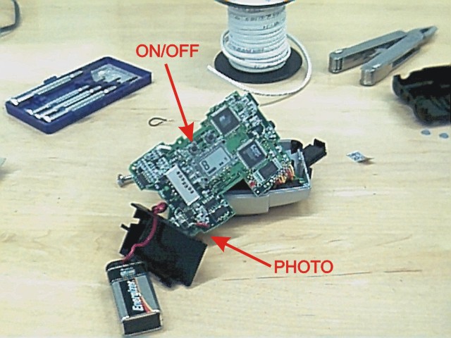
Open the Jam Cam case and remove the circuit board.
Find the ON/OFF switch and PHOTO switch.
Flip the circuit board over, so the side with the lens (not the side with the LCD) is exposed. Find the switch wires that are soldered to the back of the board. There are two short (less than 2 mm) wires for each switch.
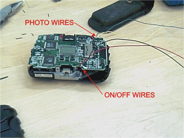
Test that you’ve found the correct wires by shorting them.
**Remove the 9V battery.**
Solder a long wire to each of the four short switch leads. Remember to remove the camera battery before soldering. This soldering is somewhat tricky. Try to use a soldering vise, and touch the iron to the board for as short a time as possible.
Remove the flashbulb by removing the solder that attaches it (so the flash doesn’t go off inside the dark camera enclosure).
Carefully reattach the camera circuit board.
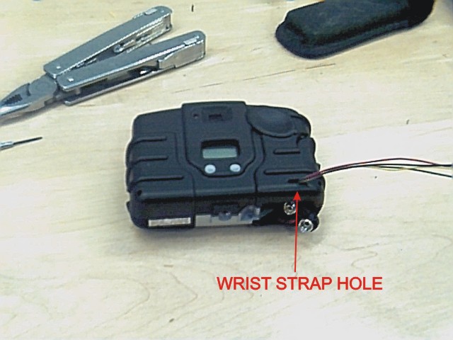
Reattach the plastic camera cover. I’ve used the wrist strap hole to feed the four wires through.
Photos on this page were taken with a JamCam at 640x480 resolution